Chemical Engineering Tutorials: April 2024

Friday, 26 April 2024

Engineering Bernoulli Equation

The energy equation for a steady flow incompressible fluid flow through a system with a stationary boundary is as follows:


The term (ΔÛ – Q) is referred to as friction loss per unit mass and is designated as ÊV. This represents the irreversible degradation of mechanical energy into thermal energy. Thus the above Equation 5 is expressed as follows:


This is known as the Engineering Bernoulli Equation.

Example

Water is pumped from a large reservoir to an elevation of 20m through a pipe of diameter 10cm as shown in the figure below and issues out of a nozzle to form a free jet. Assuming negligible frictional losses, calculate the power required to accomplish this task.


Solution


Simplification of the Engineering Bernoulli Equation

Static Fluid

For a static fluid, v = 0, thus the Engineering Bernoulli equation simplifies as follows:


This is the basic equation of fluid statics. The positive z-direction of the equation above should be taken in the direction opposite to gravity.

Perfect Fluid

A perfect or inviscid fluid has zero viscosity. Thus, under these circumstances the Engineering Bernoulli equation simplifies as follows:


The above equation is known as the Bernoulli Equation.


Wednesday, 24 April 2024

Mixing Chamber

This refers to the section where two or more streams mix. the mixing chamber does not necessarily have to be a distinct chamber. Mixing chambers can also be referred to as direct-contact heat exchangers.

An ordinary T-elbow or a Y-elbow in a shower serves as the mixing chamber for the hot and cold streams as shown below:


Considering the Y-elbow mixing chamber above with negligible kinetic and potential energies, the energy equation simplifies as follows:


Example

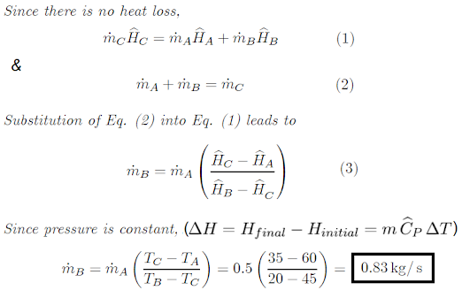
It is desired to produce a water stream at 35°C by mixing a hot water stream at 60°C with a stream of cold water at 20°C. If the mass flow rate of the hot water stream is 0.5 kg/s, determine the mass flow rate of the cold-water stream. Assume all the streams are at a pressure of 300 kPa.


Solution 1


Solution 2

Note that the enthalpy of a compressed liquid can be approximated as the enthalpy of saturated liquid at the given temperature. Therefore, from Appendix B (Table B.1) from M.D Koretsky, Engineering and Chemical Thermodynamics, Wiley, 2004.


Monday, 22 April 2024

Heat Exchanger

In this blog entry we will look into the thermodynamics of a heat exchanger. To learn more about types of heat exchangers and factors affecting performance of a heat exchanger, you can read a previous blog entry on Heat Exchangers here.

To recap, a heat exchanger is a device with two flowing streams that exchange heat without mixing. The most basic form of a heat exchanger is a double-pipe heat exchanger that consists of two concentric pipes with differing diameters. One of the fluids flows in the inner pipe while the other flows in the annular space between the two pipes. The two fluid should have a considerable temperature difference to facilitate heat transfer from hot to cold fluid through the pipe walls. 

The figure below illustrates the layout of co-current and countercurrent flow heat exchangers:


No work is produced in a heat exchanger and both kinetic and potential energy changes are negligible. The energy equation considering a heat exchanger as a system thus reduces to:

The outer shell of the heat exchanger is usually well insulated to prevent heat loss to the surroundings.


Note: For the following example, Appendices B.2 and B.4 for steam values that I have referred to in these questions was obtained from: 

M.D Koretsky, Engineering and Chemical Thermodynamics, Wiley, 2004.

Example

High pressure steam at 0.4 kg/s and 2 MPa and 450°C enters an adiabatic steady flow turbine. The work produced by the turbine is 400 hp. The exit stream from the turbine is at 40 kPa and it is fed to a heat exchanger where it is condensed at constant pressure to obtain saturated liquid. As cooling medium liquid water is used which enters the heat exchanger at 15°C and leaves at 55°C. Assume no heat losses from the heat exchanger to the surroundings.


a) What is the condition of the steam leaving the turbine?

b) Calculate the mass flow rate of the cooling water used

Solution 1


Solution 2

An alternate solution can be as follows:

Choosing the turbine and the heat exchanger as the system, the energy equation can be written and solved as follows:


Wednesday, 17 April 2024

Nozzles and Diffusers

A nozzle is a device that is specifically designed to increase kinetic energy of a high-pressure fluid at the expense of its pressure and temperature. A booster rocket is an example of a nozzle.

A diffuser is a device that increases the pressure of a fluid by reducing its speed.

Thus a nozzle and a diffuser perform in an opposite way.

As shown below, the cross-sectional area of a nozzle decreases in the flow direction to increase fluid velocity, while the cross-sectional area of a diffuser increases in the flow direction. 


For nozzles and diffusers, there is negligible change in the potential energy. Since these devices have high velocities, the time spent by a fluid particle within the devices is very short for any significant heat transfer to occur. Thus, the energy equation simplifies to:


Example

Air enters a nozzle steadily at 300 kPa and 77°C with a velocity of 50m/s, and leaves it at 100 kPa and 320m/s. The heat loss from the nozzle is estimated to be 3.2 kJ/kg of air flowing. The inlet area of the nozzle is 100 cm2. Determine:

a) The exit air temperature,

b) The exit nozzle area.


Solution


Friday, 12 April 2024

Throttling Device

These are any devices that restrict flow causing significant pressure drop in a fluid without involving any work or significantly accelerating the fluid. A common example of a throttling device is the valve in the common kitchen faucet which reduces the pressure of the water main to atmospheric pressure. 

As most throttling valves produce negligible changes in the potential and kinetic energies, the energy balance simplifies as shown:


Usually, the fluid passing through a throttling device is moving so rapidly that it does not remain within the device long enough for heat transfer to take place. Heat transfer can be considered negligible, thus the above equation simplifies as:


Since enthalpy is constant, this is an isenthalpic processDuring a throttling process, the variation of temperature as a result of the decrease in pressure is called the Joule-Thomson coefficient, µ.


In a throttling process, the temperature of a gas may decrease or increase depending on its initial state as shown:


The temperature at which Joule-Thomson coefficient changes sign is called an inversion temperature.

At higher temperatures µ < 0 and at lower temperatures µ > 0. Consequently, cryogenic applications require gas temperature to be lower than the inversion temperature.

Most gases have an inversion temperature higher than room temperature. Hydrogen, however, has an inversion temperature of − 80°C. Thus, to liquefy hydrogen, it is first necessary to decrease its temperature below − 80°C using liquefied nitrogen and then decrease its pressure by a throttling process.


Note: For the following examples, Appendix B for steam values that I have referred to in these questions was obtained from: 

M.D Koretsky, Engineering and Chemical Thermodynamics, Wiley, 2004.

Example 1

A fluid at 3.5 MPa and 350°C enters a throttling valve and leaves it at 100 kPa. Determine the exit temperature if the fluid is (a) steam, (b) air.

Solution


Example 2

Steam at 4.5 MPa and 500°C enters the turbine with a velocity of 60 m/s and its mass flow rate is 5,000 kg/h. The steam leaves the turbine at a point 3m below the turbine inlet with a velocity of 350 m/s. The heat loss from the turbine is 105 kJ/h and the shaft work produced is 950 hp. A small portion of the exhaust steam from the turbine is passed through a throttling valve and discharges at atmospheric pressure. What is the temperature of the steam leaving the valve?

Solution


Tuesday, 9 April 2024

Compressors, Pumps and Turbines

Compressors and pumps are devices used to increase the pressure of a fluid by doing work on the fluid through a rotating shaft.

While compressors are used for gases, pumps are used for liquids. A steam turbine, on the other hand, is used to convert heat energy contained in high pressure and high temperature steam into mechanical energy which can generate electricity.

Pumps are an essential part of many chemical engineering processes. They move, store, and transfer fluids and are a pivotal component of the process. Pumps can be classified into two types:

  • Positive displacement pumps – This type uses the difference in pressure between two chambers to create a force that drives liquid from one chamber to another. They are used in chemical engineering, water treatment, and food processing industries.
  • Vacuum pumps – This type is used to create a vacuum in a system. They are used in many industries, such as chemical engineering and fluid power. Vacuum pumps can be further divided into two types: positive displacement – this one uses pistons to create suction and rotary vane uses rotating vanes around a central shaft to produce suction through centrifugal force.

Compressors increase the pressure through a series of rotating discs or cylinders and is typically powered by an electric motor. It consists of two rotating cylinders (one inside the other). Compressors are used in various applications, from cars to airplanes and in chemical engineering to process and control the flow of gases.

For most compressors, pumps and turbines it is found that the changes in kinetic and potential energy terms are usually quite small in comparison to the change in enthalpy. Thus, the energy equation reduces to:


Example

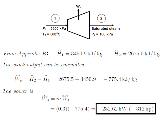
A 0.3kg/s of steam enters a steady-flow turbine at 3500 kPa and 500°C. Saturated steam leaves the turbine at 100 kPa. The turbine is well insulated so that the process may be assumed to be adiabatic. Calculate the power output of the turbine.

Solution 

Note: The Appendix B for steam values that I have referred to in these questions was obtained from: 

M.D Koretsky, Engineering and Chemical Thermodynamics, Wiley, 2004.


Continuum Mechanics

Continuum Mechanics is the study of the behavior of materials by ignoring its particulate nature.  A continuum is an area that can keep bei...