Chemical Engineering Tutorials

Wednesday, 7 July 2021

Heat Exchangers

There are several methods used to increase or decrease the temperature of a fluid. Heating of fluids is generally done using fuel fired furnaces through which the fluid in directed while cooling of fluids is done using chillers. Both of these methods require a significant amount of energy and expense to operate. Thus a cost effect method of heat exchange is needed.

A heat exchanger is such a device, which is designed to exchange heat between two flowing streams (a hot one and a cold one). The streams in a heat exchanger are generally separated by a wall which conducts heat from the hot to cold stream. This principal is illustrated below:


Types of Heat Exchangers

a) Concentric-tube Heat Exchanger

It is the simplest form of a heat exchanger, which consists of one pipe surrounding another. The hot fluid can flow in the inner pipe while the cold flows in the outer pipe or vice versa. The general form of a concentric-tube heat exchanger is shown below:


A closer look inside the concentric-tube heat exchanger shows that heat transfer occurs through convection from hot fluid to pipe wall, then by conduction through the wall and finally convection from pipe wall into cold fluid. This is summarized below:


b) Shell and Tube Heat Exchanger

In this type on part of the process flows through a tube while the other around the shell. The heat from the reaction is transferred to the gases across the tube wall. The rate of heat transfer is proportional to the following:
  1. The temperature gradient between the hot gases and the incoming gases.
  2. The total surface area of the tubes.

The figure below shows an illustration of a shell and tube heat exchanger. This heat exchanger is used in the used in the manufacture of sulfur trioxide from sulfur dioxide through the Contact Process where the excess heat warms incoming gases. 

The figure illustrates the manufacture of sulfur trioxide. This exchanger is configured in a counter current flow mode. The fluid inside the shell actually slows across the outside of the tubes i.e., crossflow due to presence of baffles on the shell side.


c) Parallel-plate Heat Exchanger

In this type, the cold and hot fluids flow on opposite sides of conducting barriers in narrow spaces between the parallel plates.

Factors affecting the performance of a Heat Exchanger

  1. The rate of heat transfer determines the size of a heat exchanger.
  2. When a chemical reaction occurs within the exchanger (like a reactor) then the residence time also needs to be considered in the design of a heat exchanger.
  3. The direction of fluid flow. When the cold and hot fluids enter from the same direction along the exchanger, the arrangement is called co-current or parallel flow. In this arrangement the maximum temperature difference between the two fluids is at the point of entry and the temperature difference significantly decreases as the fluid moves along the exchanger. This is summarized below:


When the hot and cold fluids enter from opposite sides then this is called counter current flow. In this arrangement the temperature difference between the two fluids doesn't vary as dramatically as in the co-current flow. Also, in counter current flow, the exit of the cold fluid may be hotter than the exit of the hot fluid. This is summarized below:


The decision of whether to use co-current or counter current flow is based on which of the two yields in the smallest heat exchanger to transfer a specified amount of heat. Practical issues like piping layout also affect the decision. However, most heat exchangers use the counter current flow.

Sometimes, the fluid flowing in a shell and tube heat exchanger passes from one tube end to another only once same with the fluid in the shell side. This is called a single-tube pass, single-shell pass exchanger. But it is possible to configure an exchanger to have more than one tube and shell pass as illustrated below:


Tuesday, 15 June 2021

Advantage and Disadvantage of Reactor Types

a) Tubular Flow Reactors

Used in large scale applications especially gas phase reactions.
Used for fast homogeneous and heterogeneous reactions
Suitable for continuous production and high temperature reactions.

source: https://www.tandfonline.com/doi/full/10.1080/00194506.2024.2328570

Advantages:

  • Highest conversion per unit volume.
  • Low operating labour costs
  • Continuous operation
  • Good heat transfer

Disadvantages:

  • Undesired thermal gradients may exists, hence poor temperature control
  • Shutdown and cleaning can be expensive

b) Tubular Fixed Bed Reactor

Suitable for gas phase solid catalyzed reactions i.e., gas-solid reactions.

source: https://www.researchgate.net/figure/Multi-tubular-fixed-bed-reactor-design_fig3_387160903

Advantages

  • Highest conversion per unit mass of catalyst
  • Low operating labour cost
  • Continuous operations 

Disadvantages:

  • Undesired thermal gradients may exists, hence poor temperature control.
  • Channeling may occur. This is caused by uneven or loose packing of solid phase material inside the column meaning liquid flowing experiences less resistance hence higher flow rates. The liquid thus passes through voids within the bed rather than having contact with the packed material. This lowers the performance of the column.
  • It is difficult to service and/or clean the unit.

c) Batch Reactors

Used in small scale productions e.g. laboratory processes. Widely used in pharmaceutical and fermentation processes.

source: https://www.essentialchemicalindustry.org/processes/chemical-reactors.html 

Advantages:

  • High conversion per unit volume for one pass
  • Flexibility of operation. The same reactor can be used to produce one product at one time and another product in the next time.
  • Easy to Clean

Disadvantages:

  • High operation costs i.e. labour costs
  • The quality of the product varies as compared to continuous operations


d) Semi-batch Reactor

Suitable for small scale production. 

Two phase reactions like gas-liquid reactions can be carried out. 

source: https://chemicalengineeringworld.com/types-of-reactors/

Advantages:

  • High conversion per unit volume for one pass.
  • Good selectivity. The feed can be controlled to minimize side reactions.
  • Flexibility of the operation can be used with a reflux condenser for solvent recovery or bubble type reactions. 

Disadvantages:

  • High operation costs i.e. labour costs.
  • The quality of the product varies as compared to continuous operations

e) Continously-stirred Tank Reactors (CSTR)

Suitable for liquid phase, gas-liquid, solid-liquid reactions

source: https://www.comsol.com/blogs/simulating-an-ideal-stirred-tank-reactor-system

Advantages:

  • Continuous operation
  • Good temperature control
  • Easily adaptable to two phase (gas-liquid) reactions
  • Reaction control is possible
  • Easy to construct
  • Low labor costs
  • Easy to clean

Disadvantages:

  • Lowest conversion per unit time
  • By-passing channeling is possible with poor agitation. 


f) Fluidized Bed

Suitable for gas-solid reactions and gas-solid catalyzed reactions

source: https://www.sciencedirect.com/science/article/pii/S136403211930797X

Advantages:

  • Good mixing
  • Good uniformity of temperature
  • Continuous regeneration of the catalyst by using an auxiliary loop.

Disadvantages:

  • Bed fluid mechanics not well known
  • Severe agitation can result in catalyst destruction, dust formation and carry over in product streams
  • Uncertain scale up


Continous Flow Reactors


Wednesday, 5 May 2021

Batch Reactors

The theory behind batch reactors is discussed here
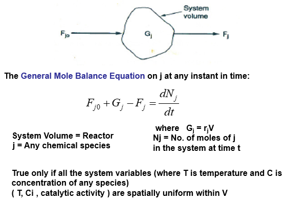
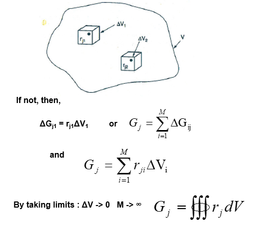
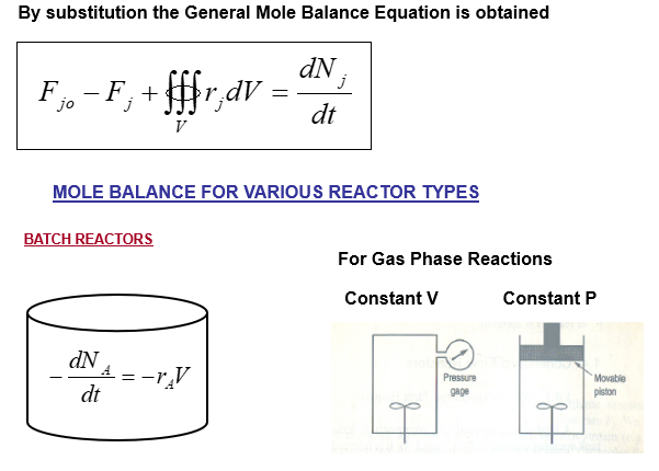
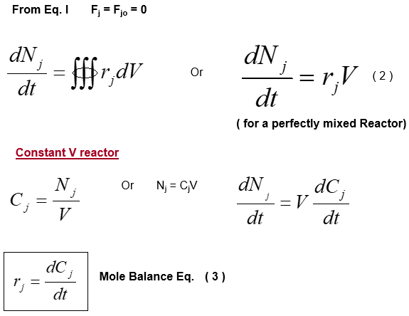
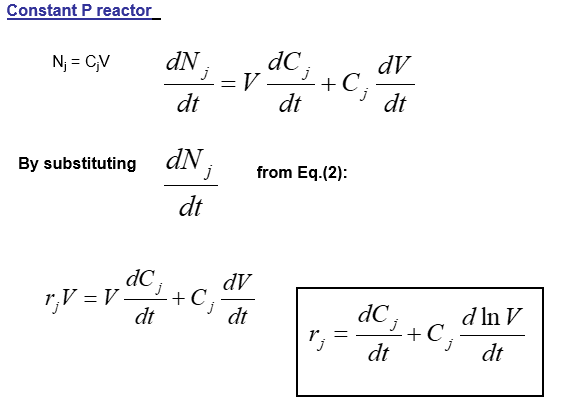
The mathematical relations for batch reactors are discussed below:

Published from Blogger Prime Android App

Saturday, 1 May 2021

Chemical Reactors

The design of a reactor is determined by many factors but the most important are the thermodynamics and kinetics of the chemical reactions being carried out.

The two main types of reactor are batch and continuous.

1) Batch reactors

Batch reactors are mostly used for the reactions being carried out in a laboratory with the reactants being placed in a test-tube, flask or beaker. They are mixed together, often heated for the reaction to occur and then cooled. The products are poured out and purified if necessary.
This procedure is also carried out in the industrial scale with the key difference being one of size of reactor and the quantities of reactants.
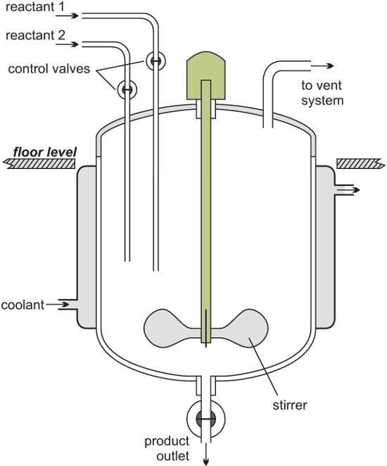
The following image shows a batch reactor.


Published from Blogger Prime Android App

After the reaction, the reactor is cleaned to ready it for another batch of reactants to be added.
Batch reactors are usually used when a company wants to produce a range of products involving different reactants and reactor conditions. They can then use the same equipment for these reactions.
Examples of processes that use batch reactors include the manufacture of colorants and margarine.

2) Continuous reactors

Alternatively, the reactant feed can be fed continuously into a reactor at one point, then the reaction occurs in the reactor and the product and byproducts withdrawn from another point. The inlet flow must he equal to the outlet flow.
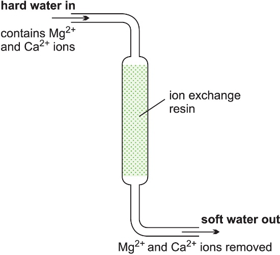
Softening hard water is an example of a continuous process. Hard water is passed through a tube containing an ion-exchange resin. The reaction occurs down the tube and soft water pours out at the exit. This is summarized below:


Published from Blogger Prime Android App

Continuous reactors are general used to produce large quantities of a chemical and needs to operate for several months without a shutdown.

The residence time in the reactor is controlled by the amount of reactant fed into the reactor. Since the volume is fixed, the residence time in the reactor is easy to control.

The products from a continuous process tend to have a more consistent quality since the reaction parameters like residence time, temperature and pressure are easily controlled than in batch operations.

The amount of waste produced is also less and it requires much lower storage of both raw materials and products hence its a more efficient operation. This means that the capital costs per ton of product produced are lower.

The main disadvantage is their lack of flexibility as the reactor built is rarely used to perform a different chemical reaction.

There are several types of continuous reactors:

(a) Tubular reactors

In a tubular reactor, fluids (gases and/or liquids) flow at high velocities. As the reactants flow along a heated pipe, they are converted to products. At these high velocities, the products are unable to diffuse back and there is little or no back mixing. The conditions are referred to as plug flow. This reduces the occurrence of side reactions and increases the yield of the desired product.

With a constant flow rate, the conditions at any one point remain constant with time and changes in time of the reaction are measured in terms of the position along the length of the tube.

The reaction rate is faster at the pipe inlet because the concentration of reactants is at its highest and the reaction rate reduces as the reactants flow through the pipe due to the decrease in concentration of the reactant.

Tubular reactors are used, for example, in the steam cracking of ethane, propane and butane and naphtha to produce alkenes.

(b) Fixed bed reactors

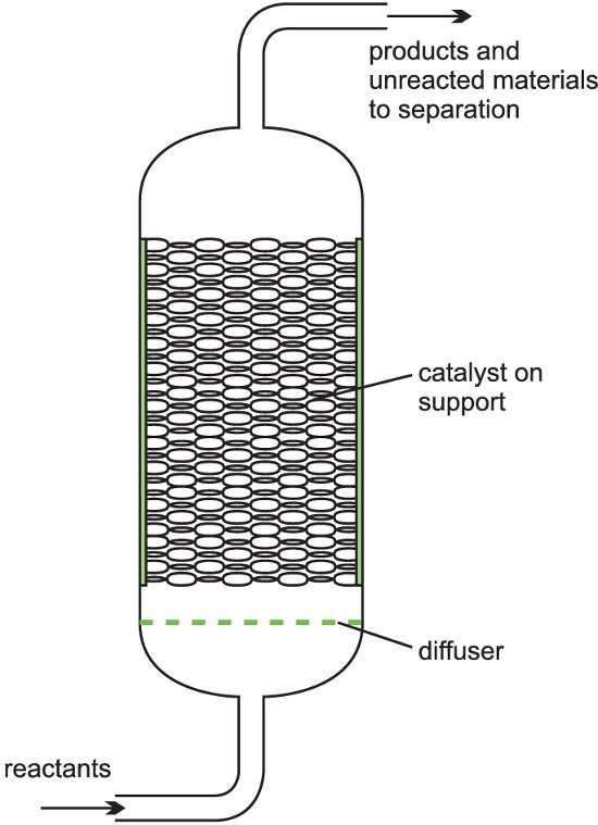
It is described as a fixed bed of catalyst. A heterogeneous catalyst is used where gases flow through a solid catalyst (which is often in the form of small pellets to increase the surface area). The figure below shows a fixed bed reactor. 


Published from Blogger Prime Android App

These type of reactors are used in the following processes:

  • The manufacture of sulfuric acid through the Contact Process, with vanadium(V) oxide as catalyst.
  • The manufacture of nitric acid.
  • The manufacture of ammonia through the Haber Process, with iron as the catalyst. 
  • The catalytic reforming of naphtha to produce branched chain alkanes, cycloalkanes and aromatic hydrocarbons using a platinum or a platinum-rhenium alloy on an alumina support.

(c) Fluid bed reactors

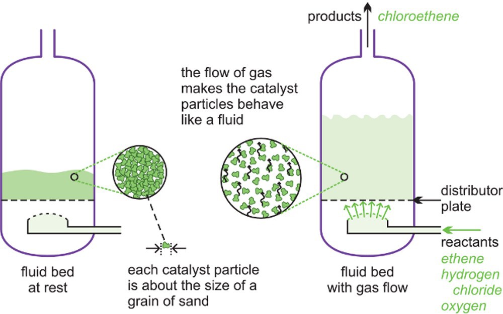
A fluid bed reactor is sometimes used whereby the catalyst particles, which are very fine, sit on a distributor plate. When the gaseous reactants pass through the distributor plate, the particles are carried with the gases forming a fluid. This ensures very good mixing of the reactants with the catalyst, with very high contact between the gaseous molecules and the catalyst and a good heat transfer. This results in a rapid reaction and a uniform mixture, reducing the variability of the process conditions.


Published from Blogger Prime Android App

Above is an illustration of a fluid bed reactor. On the left hand side, the particles are at rest. On the right hand side, the particles are now acting as a fluid, as the gaseous reactants pass through the solid.

It is used in the following processes:
  • The oxychlorination of ethene to chloroethene (vinyl chloride)
  • The feedstock for the polymer poly(chloroethene) (PVC). The catalyst is copper(II) chloride and potassium chloride deposited on the surface of alumina.
  • The catalytic cracking of gas oil to produce alkenes (ethene and propene) and petrol with a high octane rating.
These reactors are larger than fixed bed reactors and are more expensive to construct. However, it is easier to control the conditions and the process is more efficient.

(d) Continuous stirred tank reactors, CSTR

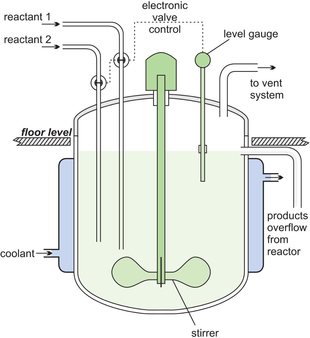
In a CSTR, one or more reactants are introduced into a reactor equipped with a stirrer and the products are removed continuously. The reagents are stirred vigorously for good mixing to ensure there is a uniform composition throughout. The composition at the outlet is the same as in the bulk in the reactor. These are exactly the opposite conditions to those in a tubular flow reactor where there is virtually no mixing of the reactants and the products. The figure below shows a CSTR.


Published from Blogger Prime Android App

A steady state must be reached so that the flow rate into  and out of the reactor are equal or the tank would empty or overflow. The residence time is calculated by dividing the volume of the tank by the average volumetric flow rate.

A CSTR reactor is used in the production of the amide intermediate formed in the process to produce methyl 2-methylpropenoate.

A variation of the CSTR is the loop reactor which is relatively simple and cheap to construct. These are used in the manufacture of poly(ethene) and poly(propene). 


Future of reactors

Microreactors are the future of chemical production where the size of a reactor is about the size of a desktop computer. The reduced size will lead to reduced capital costs and reduced amount of chemicals used at any one time resulting in safer processes. 
The temperature can be kept constant easily due to larger surface area for a volume allowing more efficient heat transfer to the surroundings even for exothermic reactions.
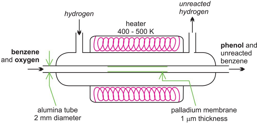
There is considerable amount of research being carried out in developing microreactors. One example is the possibility of the direct conversion of benzene to phenol. A mixture of benzene and oxygen is fed through an alumina tube, packed with palladium at 350-400 K and hydrogen gas is passed over it. The figure below shows a microreactor being used to produce phenol from benzene.
Published from Blogger Prime Android App

Hydrogen permeates through the alumina tube, and is converted to atomic hydrogen by the palladium catalyst. The hydrogen atoms react with oxygen, releasing reactive oxygen species, such as hydroxyl radicals, which in turn react with the benzene to form phenol.

Another development is known as oscillatory flow mixing. Chemical engineers are designing reactors where the fluids to be reacted are oscillated inside a reactor with baffles at frequencies between 0.5 and 15 Hz with amplitudes in the range 1 to 100 mm. This allows for very effective mixing of the reactants and also for heat to be transferred to the surroundings. This gives similar conditions to those in plug flow which are otherwise difficult to achieve with small quantities of materials.


Friday, 9 April 2021

Process Calculation Examples

Example 1

The side product of a chemical company is a mixture with 82 weight % of species A, and the remaining is species B. In this mixture, species A is the valuable component. If this mixture is sold with this composition, its price is 1.12 USD per kg. However, if the percentage of species A can be increased to 96%, the price in the market will be 1.58 USD per kg. It is proposed that a stream of species C will be used to strip the species B as shown below. In this process, 2 kg of C should be used for each kg of B entering the process.

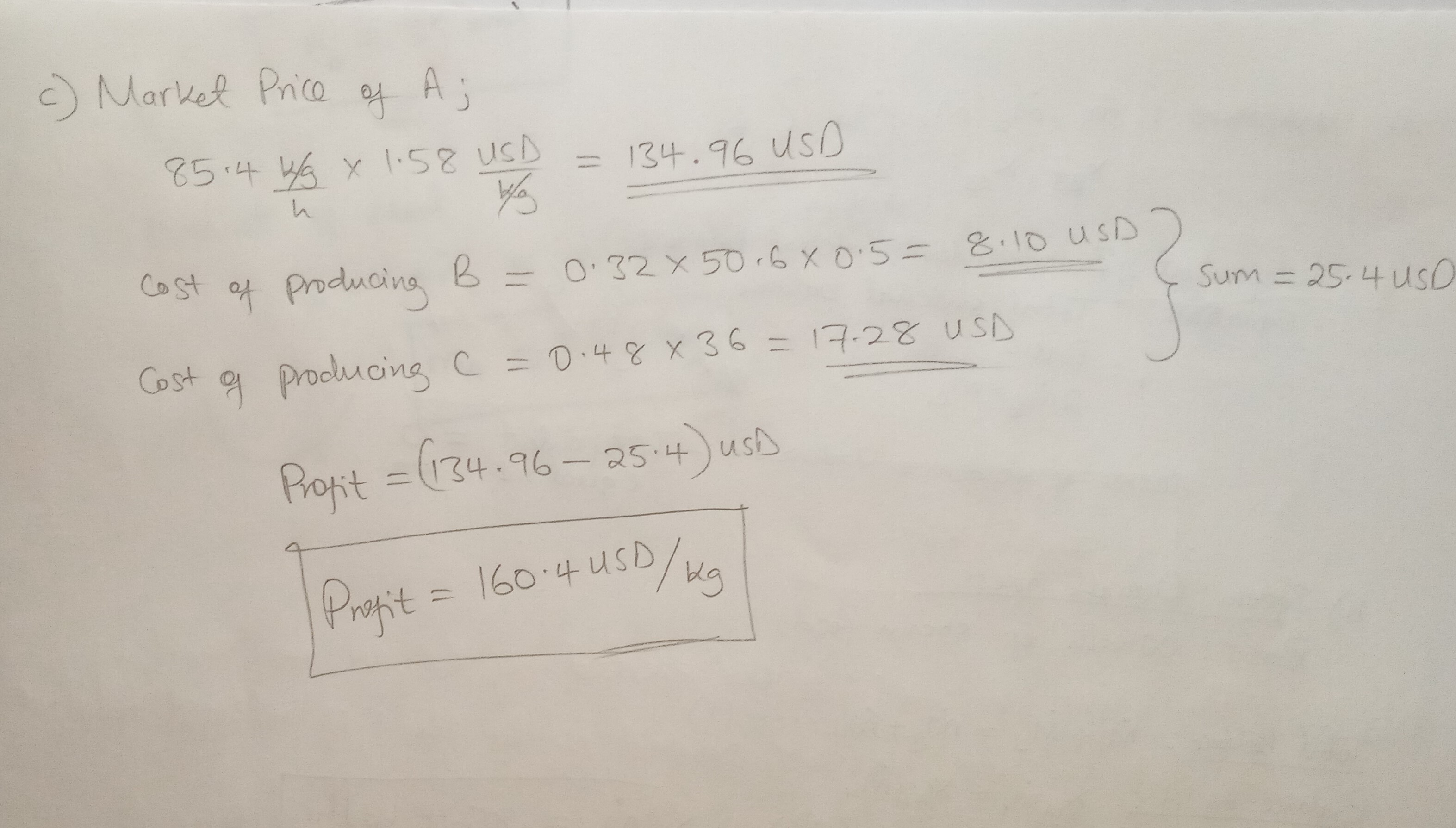
As a chemical engineer, you are requested to show whether this investment is profitable or not. The cost of species C is 0.48 USD per kg and the production cost (including energy, labour, depreciation of equipment and all others) is 0.5 USD per kg of B stripped (i.e. kg of B in stream 3). Follow these steps to solve this problem:
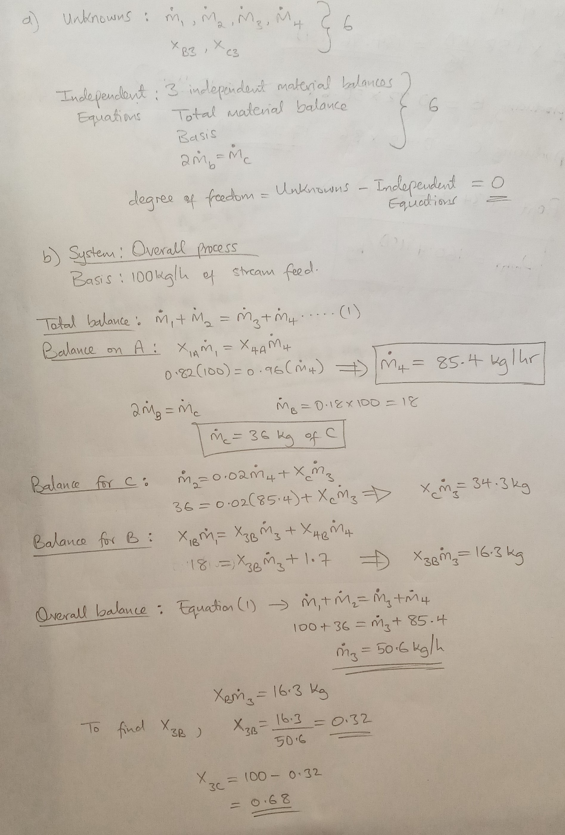
a) Determine the degree of freedom,

b) Determine all the flowrates and compositions,

c) Calculate the production cost of stream 4 per kg and compare it with the market price of mixture with 96% species A

Solution

 Published from Blogger Prime Android App

 Published from Blogger Prime Android App

Example 2

CO combines with Cl2 to form COCl2 gas. The feed to a reactor operating at steady state is a mixture of only CO and Cl2. After the reaction the product contains 12 mol COCl2, 3 mol Cl2 and 8 mol CO.

a) What is the percent excess,

b) What is the conversion of the limiting reactant,

c) What is the amount of feed in kg.

Solution


Sunday, 4 April 2021

Introduction into Reaction Engineering

Usually, a Chemical Engineer is hired to:

  • maintain and operate a process
  • fix some perceived problem
  • increase capacity or selectivity at minimum cost
  • Searching for alternate processes to replace old ones
  • Finding ways to make a product from different feedstocks
  • Reducing or eliminating a troublesome by product


Some of the major parameters in the design of chemical reactors include:

Reaction Rate

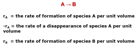
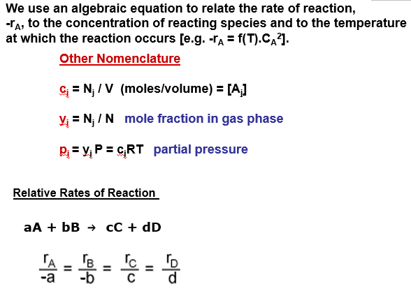
This is the rate at which a species loses its chemical identity per unit volume. The rate of a reaction can be expressed as the rate of disappearance of a reactant or as the rate of appearance of a product. Consider species A being converted to product B:

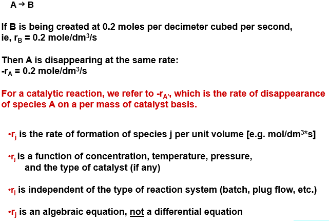
If B is being created at 0.2 moles per decimeter cubed per second, ie,

rB = 0.2 mole/dm3/s

Then A is disappearing at the same rate:

-rA = 0.2 mole/dm3/s

For a catalytic reaction, we refer to -rA, which is the rate of disappearance of species A on a per mass of catalyst basis.

Let’s assume that rj is the rate of formation of a species j per unit volume e.g., mol/dm3*s. The rj is:

  • a function of concentration, temperature, pressure and the type of catalyst (if any)
  • independent of the type of reaction system (batch, plug flow, etc.)
  • is an algebraic equation, not a differential equation. 


Published from Blogger Prime Android App

Published from Blogger Prime Android App

Published from Blogger Prime Android App

Published from Blogger Prime Android App

Published from Blogger Prime Android App

Published from Blogger Prime Android App

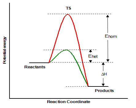
Catalysts are an important aspect of reaction engineering. They alter the speed of a reaction by lowering the activation energy of a reaction. The activation energy of a reaction is the amount of energy needed to produce a forward or reverse reaction. In the following figure we can see the activation energy of a non catalytic reaction (red line), while the green line represents the same reactions activation energy when a catalyst is used.

Published from Blogger Prime Android App

Published from Blogger Prime Android App

Examples 

Published from Blogger Prime Android App

Published from Blogger Prime Android App

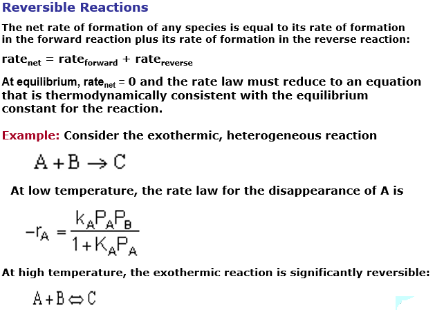
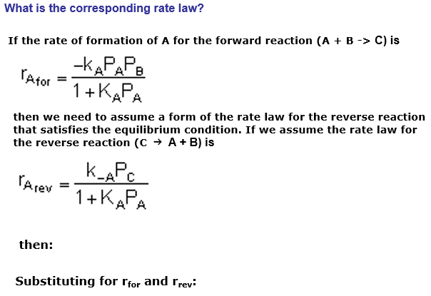
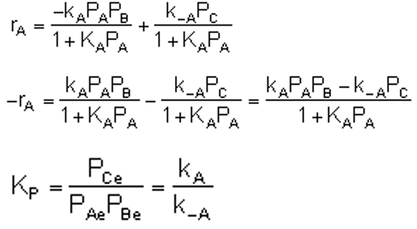
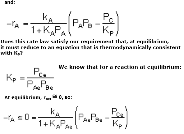
What are reversible reactions?

Published from Blogger Prime Android AppPublished from Blogger Prime Android App

Published from Blogger Prime Android App

Published from Blogger Prime Android App

Published from Blogger Prime Android App

Energy Equation in Flow Systems

When energy crosses the boundary of a system, the energy in the system changes by an equal amount. Thus a decrease in the energy of a system...