How can you convert heat into mechanical energy and work?
- One can use a steady-state flow device like a turbine where the thermal energy of a flowing fluid can be converted to mechanical energy.
- Another technique is the use of a thermodynamic cycle. In this process, a working fluid like air or steam undergoes a series of state changes and finally returns to its initial state.
The Carnot cycle is the most efficient thermodynamic cycle where an ideal gas in a frictionless piston-cylinder device undergoes the following 4 reversible successive processes:
- The ideal gas undergoes an isothermal and reversible expansion through the addition of heat from a hot reservoir at a temperature, TH,
- The adiabatic and reversible expansion of the ideal gas,
- The ideal gas undergoes an isothermal and reversible compression by discarding heat to a cold reservoir at a temperature, TC,
- And finally, the adiabatic and reversible compression of the ideal gas to its initial state.
This
can be schematically represented as follows:

This
process can also be graphed onto a P-V graph as shown below:

If
we consider our system as an ideal gas in a frictionless piston-cylinder
assembly, the analysis of the Carnot cycle is as follows:
Process 1 to 2 (Reversible isothermal expansion at TH)
Let
us take the 1st law of thermodynamics for a closed system and work
done by an ideal gas:

Process 2 to 3 (Reversible Adiabatic Expansion)
Once
again let us take the 1st law of thermodynamics for a closed system
and work done by the ideal gas:

Process 3 to 4 (Reversible Isothermal Compression)
Once
again let us take the 1st law of thermodynamics for a closed system
and work done by the ideal gas:

Process 4 to 1 (Reversible Adiabatic Compression)
Once
again let us take the 1st law of thermodynamics for a closed system
and work done by the ideal gas:

Thus, if we look at the net work output of the Carnot cycle,

If we apply the first law of thermodynamics to the Carnot cycle:

The Efficiency of Carnot Cycle, η
The efficiency, η, can be derived as follows:

Since the processes 2 to 3 and 4 to 1 are reversible and adiabatic, equation 17 can be further simplified as follows:

If we combines Equations 19 and 20 we get the following equation 21:
 (21)
(21) The Carnot cycle is the most efficient heat engine operating between two constant heat reservoirs TH and TC. A heat engine is any mechanism that operates cyclically with the primary purpose to partially convert heat into work.
Note that: Wnet = QH - QC (22)
Using this new notation,
Equations 16 and 19 combine as follows:

Substituting Equation 22 into 23 we get:

Finally, with all these new notations, we can represent the Carnot Cycle in a simpler way as shown:

Solved Examples
Example 1
A Carnot cycle receives 1000 kJ of heat at 800°C and rejects heat at 300°C. Calculate the work output.
Solution
From Equation 23:

Substituting the provided values into the above equation:

Thus:
Wnet = 466 kJ
Example 2
Suppose an iceberg weighing 1010 kg drifts into the Gulf stream which has a temperature of 22°C. If we operate a Carnot heat engine using the Gulf stream as a heat source and the iceberg as a cold sink, what is the work output that could be generated while the iceberg is melting?
Solution
Assume that the temperature of the iceberg is 0°C and the heat of fusion for ice is 334,880 J/kg. Take the iceberg as the heat sink.
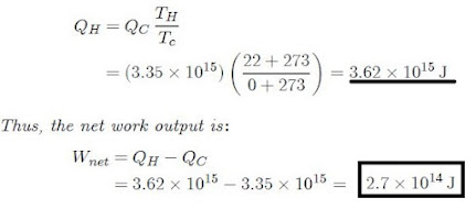
The amount of heat rejected to the sink is:
QC = (1010) (334,880) = 3.35 × 10¹⁵ J
The amount of heat absorbed can be calculated using equation 24: